Artstation Project Page: https://www.artstation.com/artwork/xzwa3r
Hello!
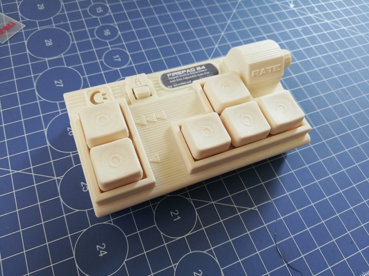
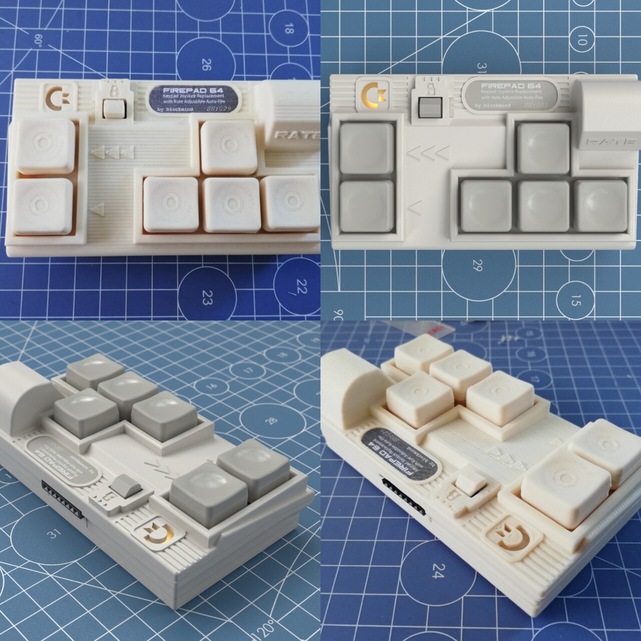
Lately as a hobbyist, I got into electronics in basic level. This time I made a keypad for joystick replacement for my Commodore 64.
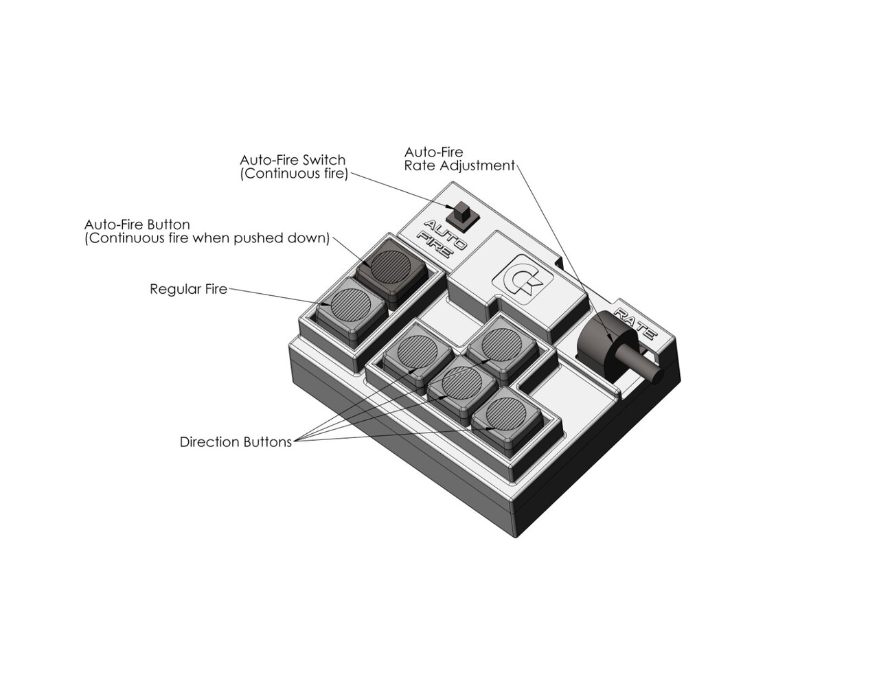
Joysticks are hard to use on many games since we got used to keyboard and gamepad use by PC and console gaming. So I tried to create a device to be used on joystick ports and will work as a keyboard arrow key arrangement.
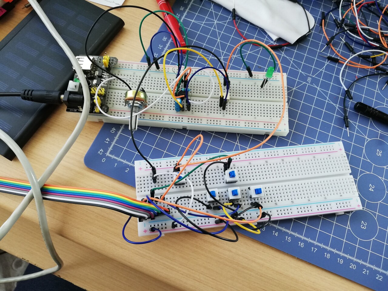
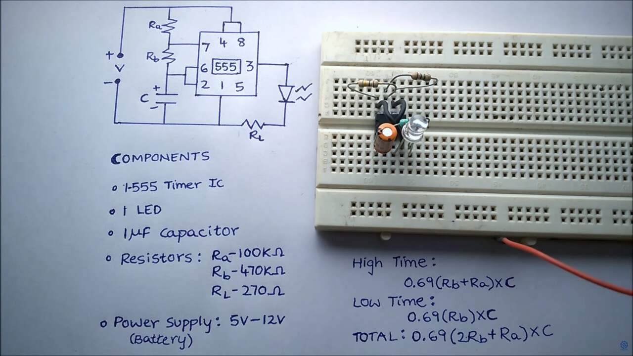
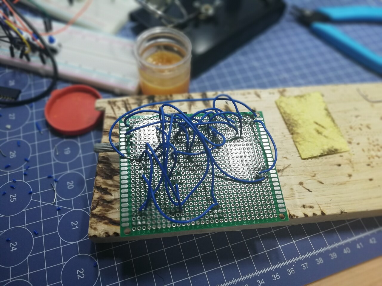
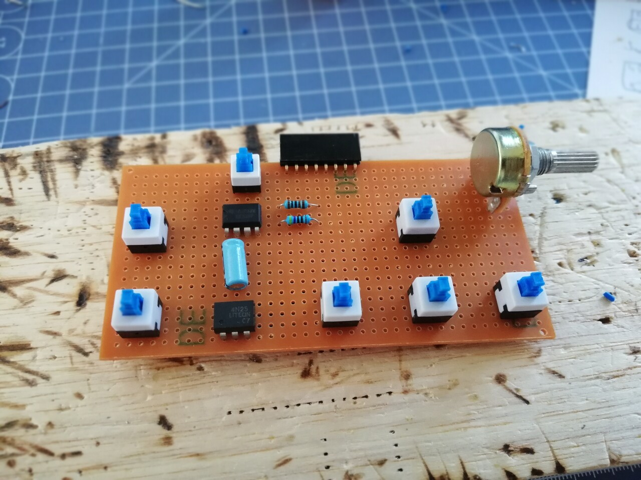
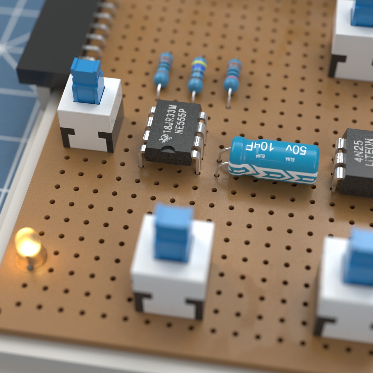
My first attempt was just for operational stability. I used a prototyping board and used 8 x 8mm buttons and a 7 x 7mm switch, few resistors and an 555 Timer IC. 555 Tımer IC is used for making frequent flows. They used basicly for making blinking lights, for example.
It compares 2 resistors and defines on and off times by a capacitor. There is a formulation for the on and off times. Which is covered on this video: https://www.youtube.com/watch?v=gTn_HmzXYLo
So I decided to use this 555 Timer IC on auto-fire of my keypad. But instead of static resistors and static rapid fire, I replaced on of the resistors with a potantiometer which is an adjustible resistor. So I would be able to change the frequency of my auto-fire.
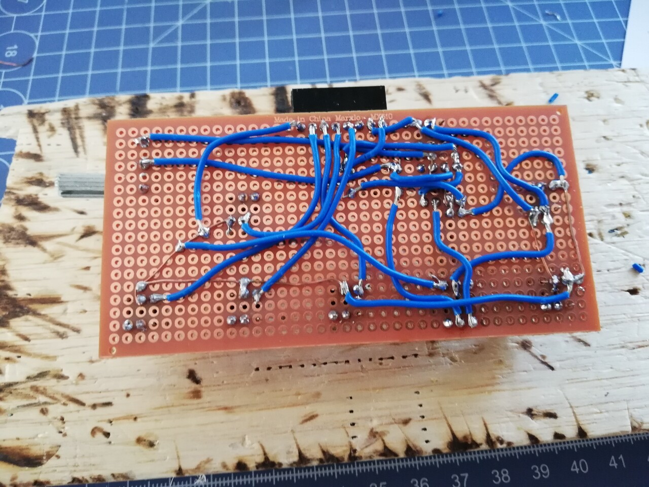
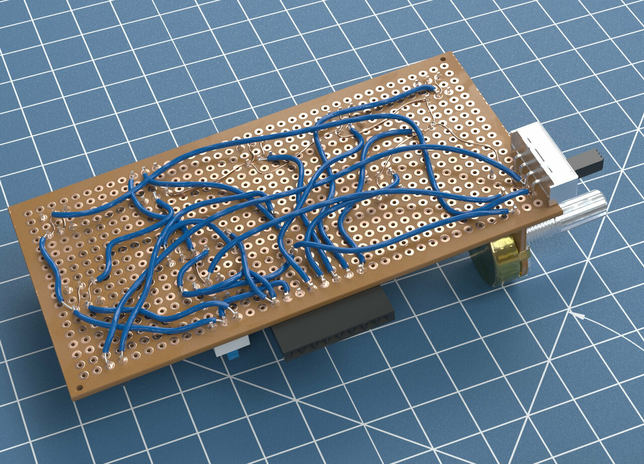
Quickly I assembled a circuit and made the connections with cables.
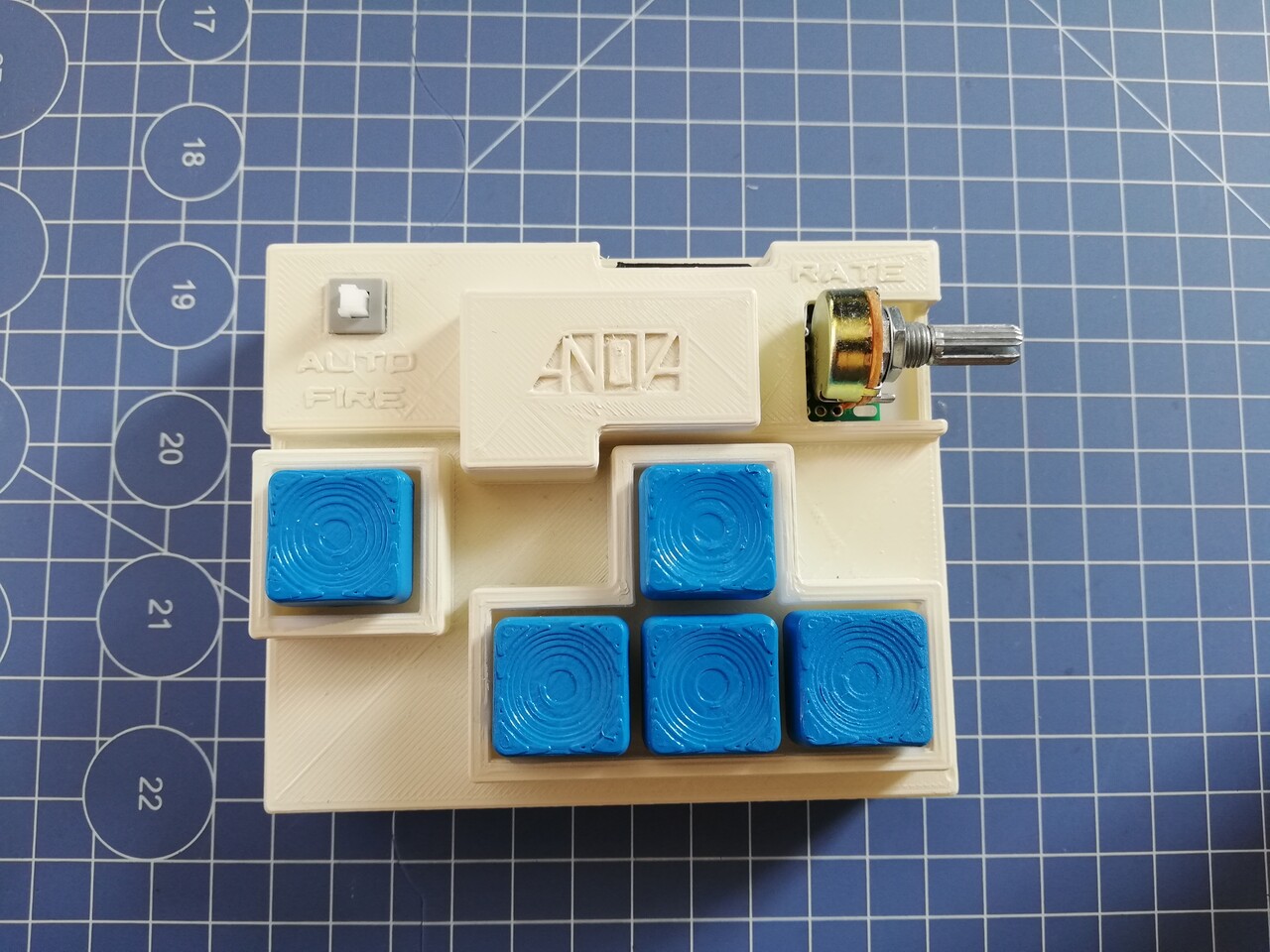
I used very cheap and generic buttons on this one. So it will be a challenge to make a usable keypad with these. Because production abilities are limited with my home and my entry level 3d printer :) So I moved on to create the case and the buttons for that circuit.
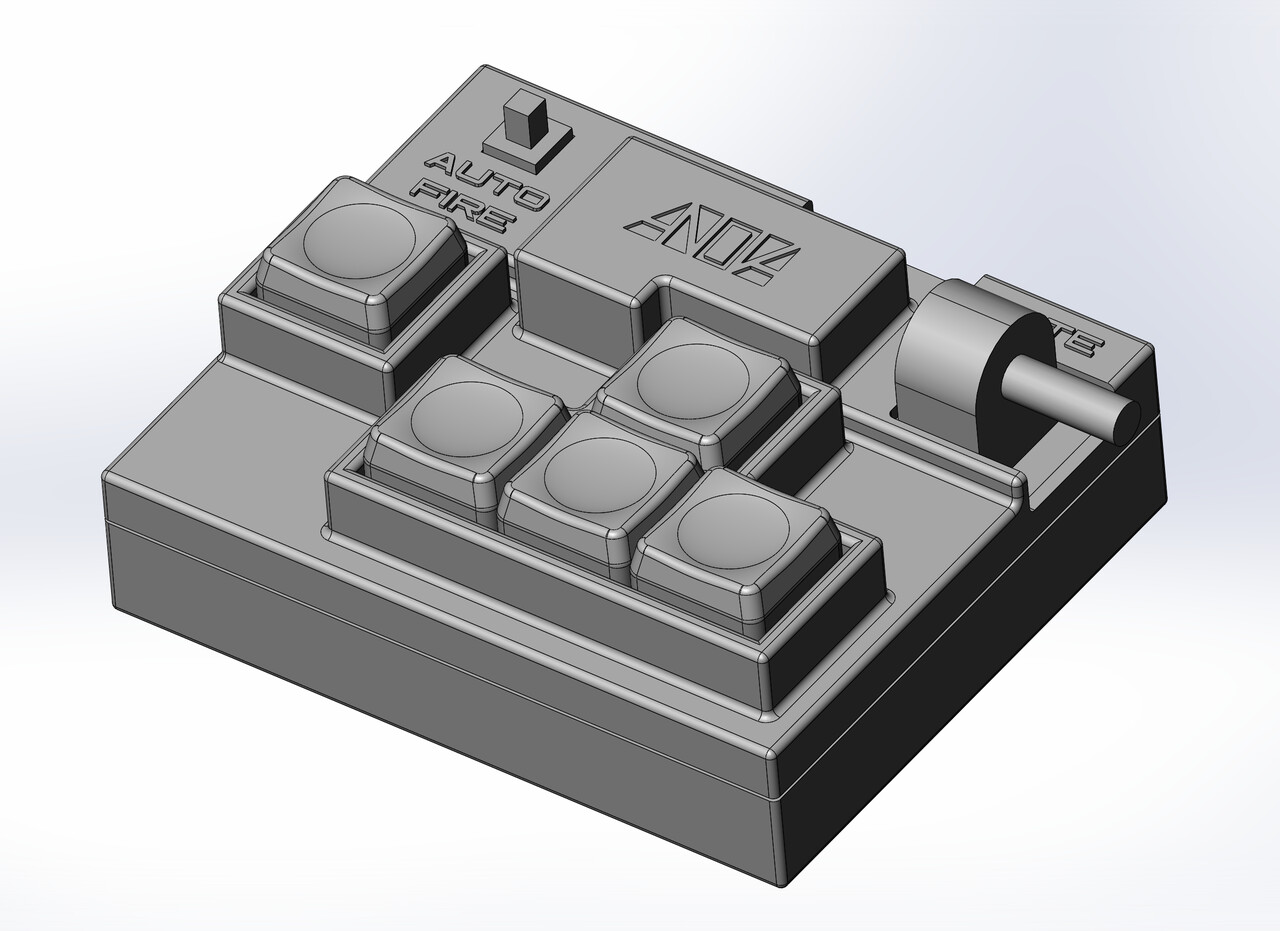
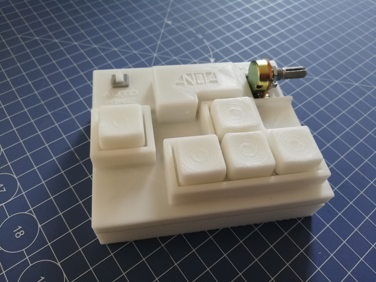
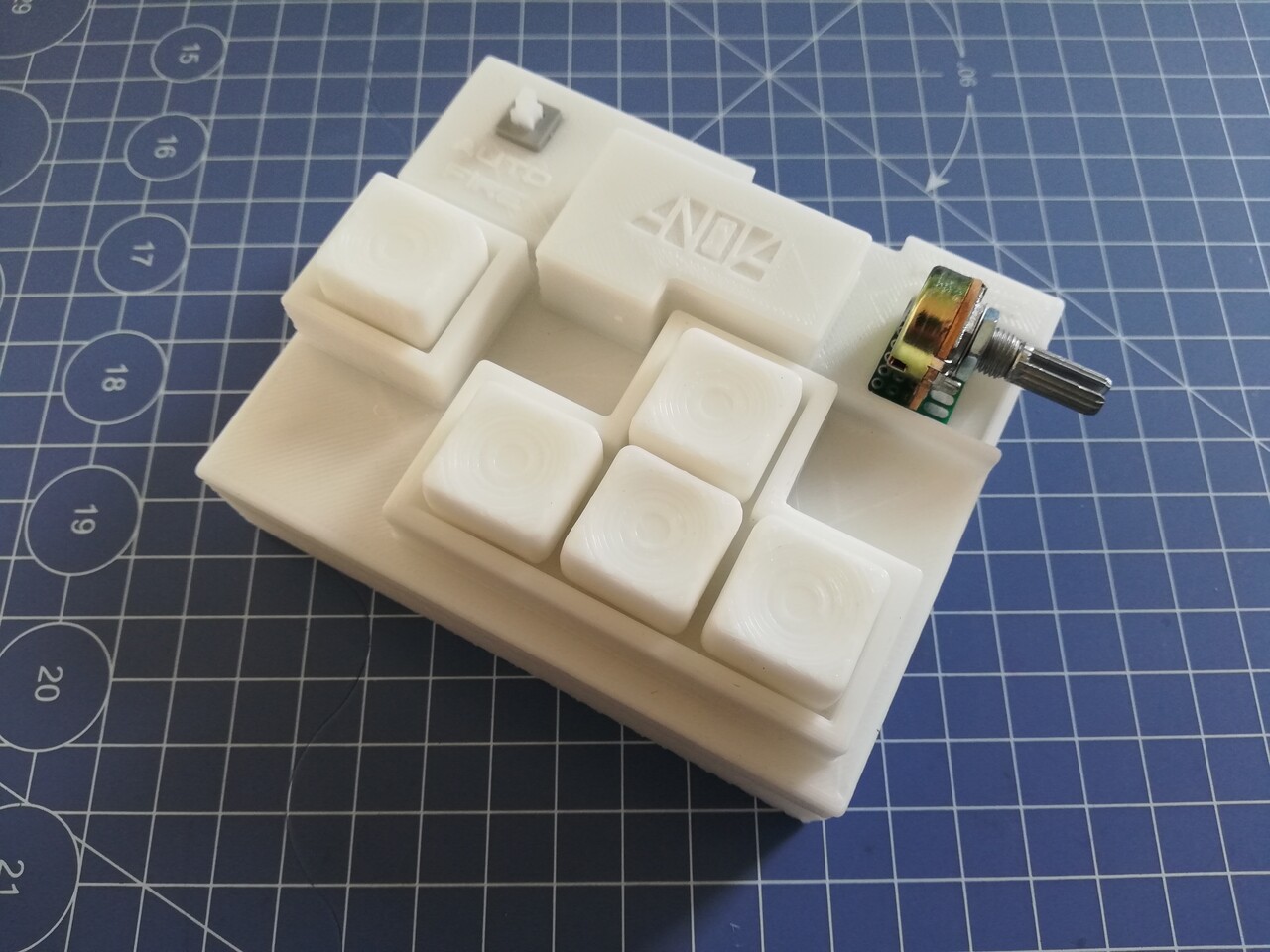
This is the first design of the keypad.
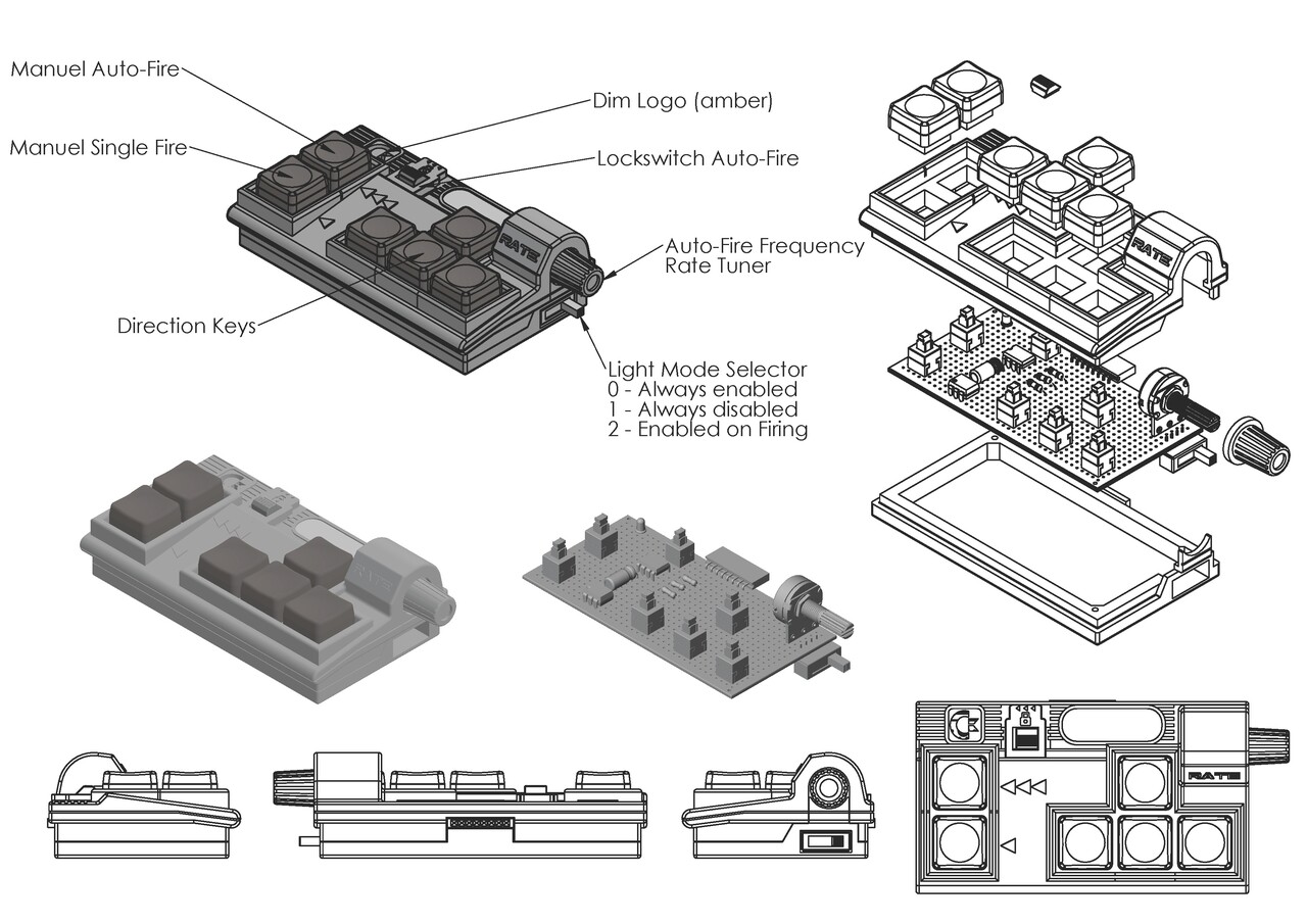
After that first design. I decided to add a second button for manually activate the auto fire and this was the drawing of it.
After the acceptible success of gameplay satisfaction level on that device, it was time to make a more cool design.
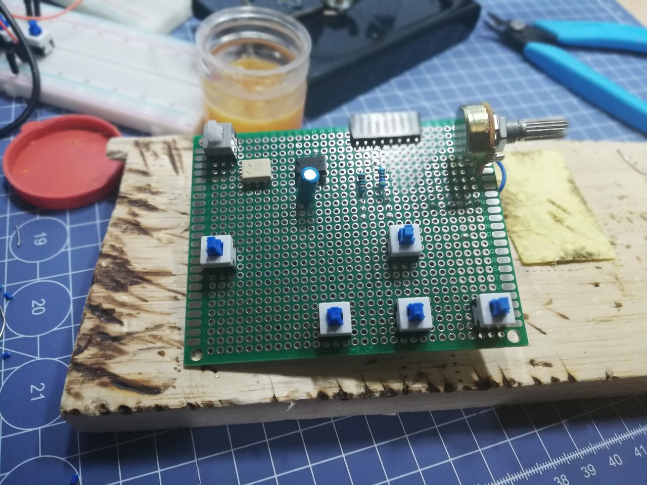
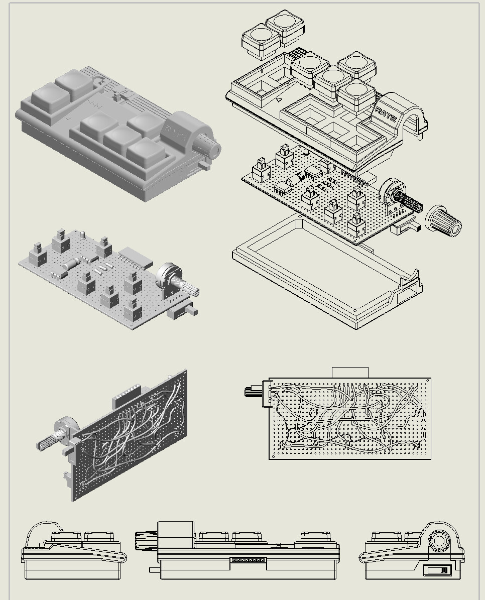
To do that, first I should create a smaller design on the board. So I measured the old one with the button offsets and clearances to the button walls and finally made this circuit.
I soldered the cables by snapping them to the board this time. To make a slim case aspect to the previous one.
This is a soldering timelapse:
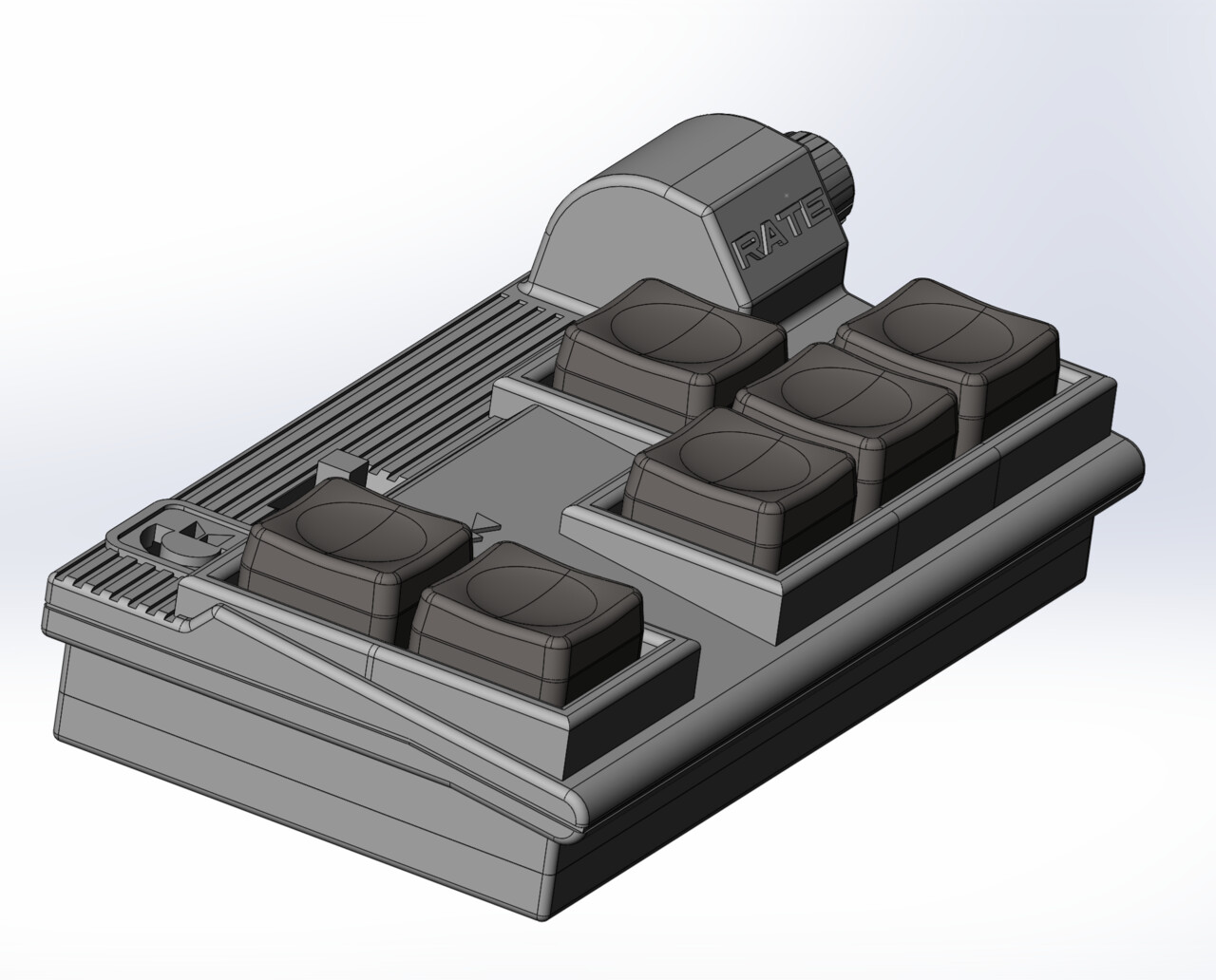
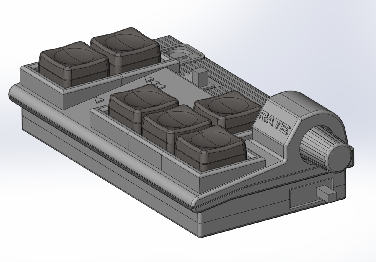
I revised and re-created the 3d model again to comply with this new board.
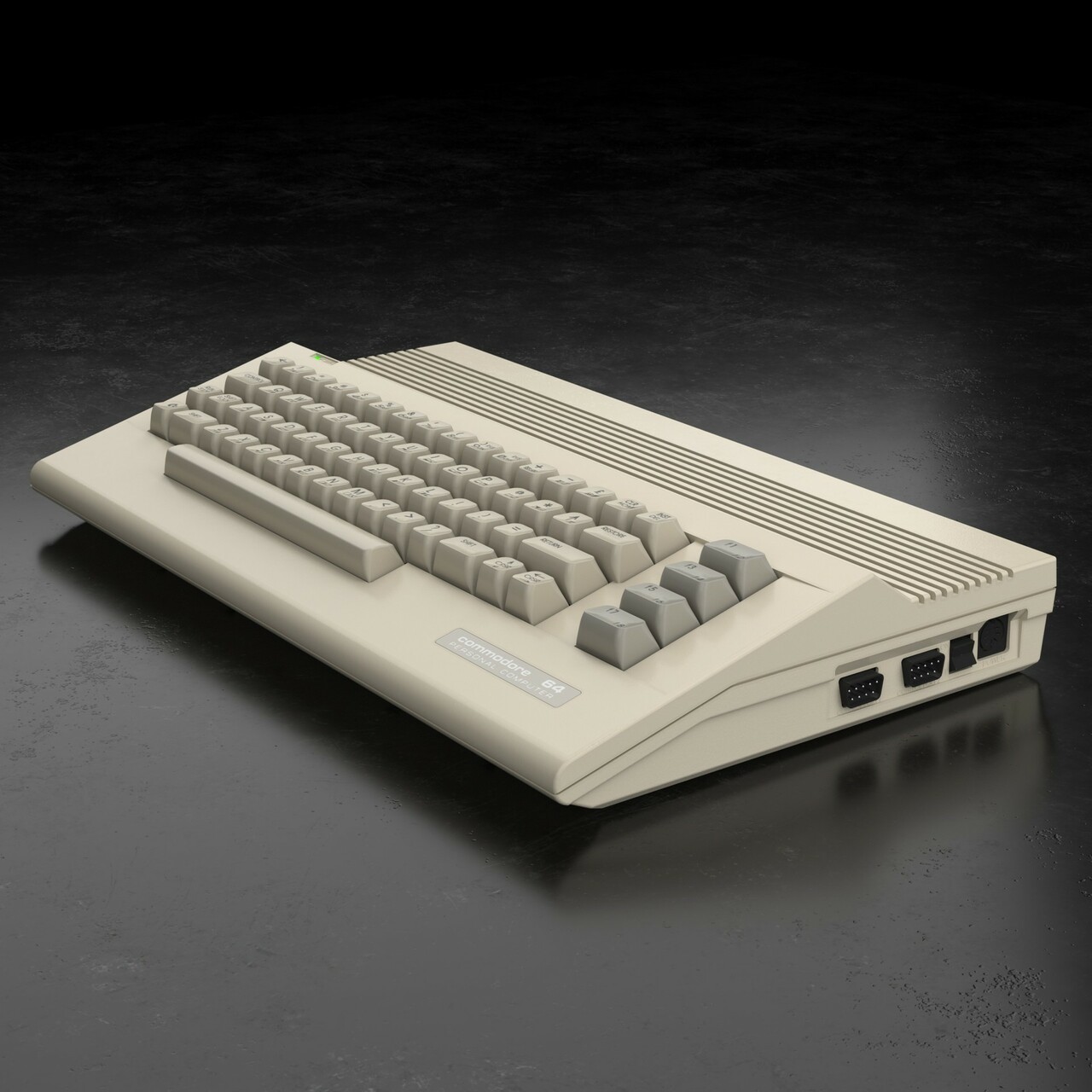
I made a resemblance with the Commodore 64C cases on an hardly recognizable level.
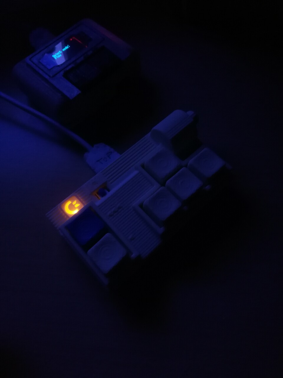
I added an LED to the new case with 3 adjustable modes. First I added this for to make it blink when it's fired on the keypad but many people may not love it so I decided to add a switch to disable the LED. But some friends suggested that to make it fully ON if it's needed. So I added a 3 way switch to the board.
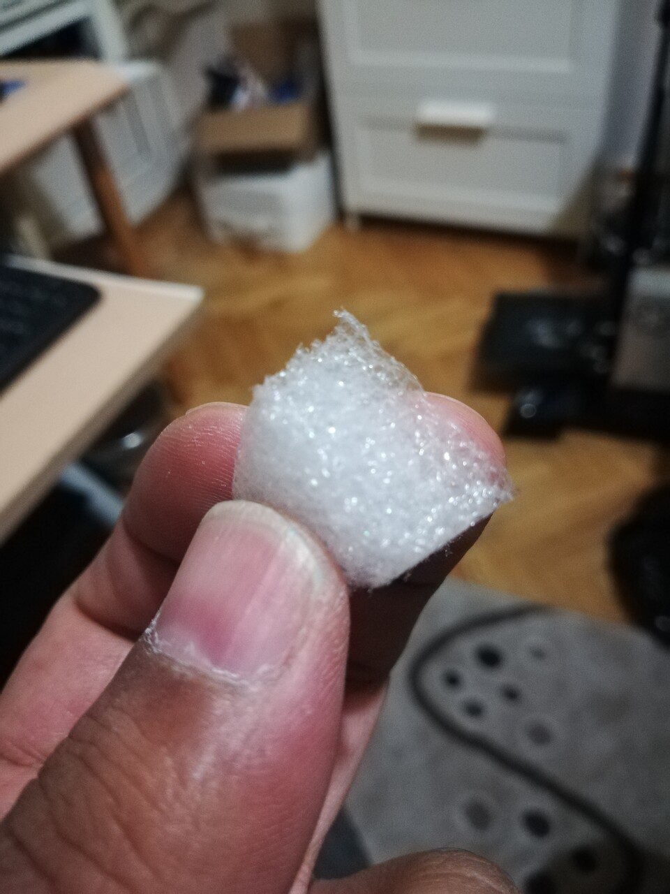
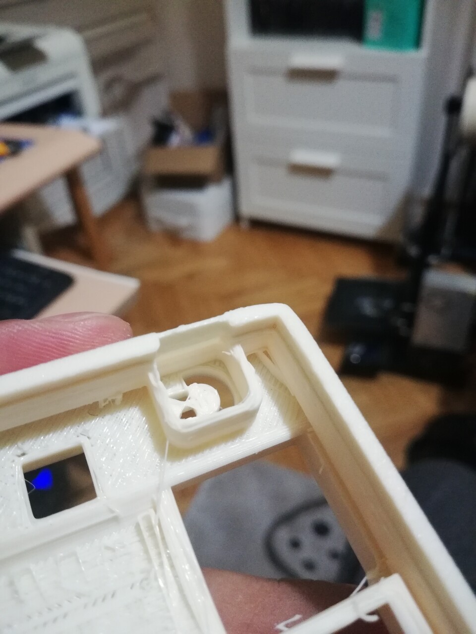
I designed the LED window as a Commodore logo and used some foam behind the window to make the light scatter inside to get soft and well distributed light.
Result is amazing!
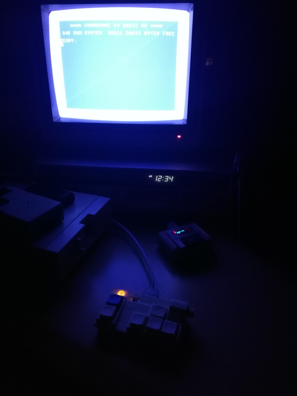
And this is the usage of the device on my Commodore 64.
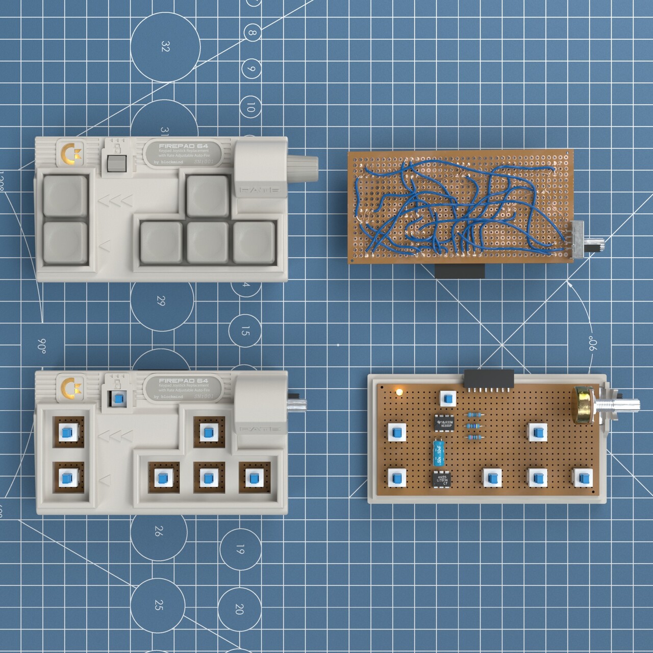
So this was the end of the device creation process. Next, I decided to visualize back all the details I created so far to make some practice of my texturing and modeling skills.
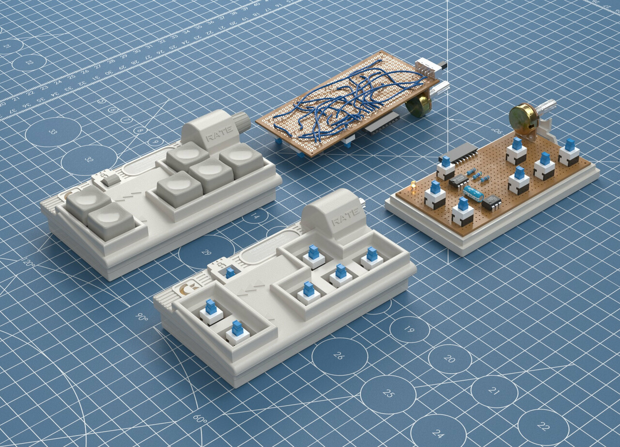
This time I modeled every detail of the electronic board, instead of creating blocks.
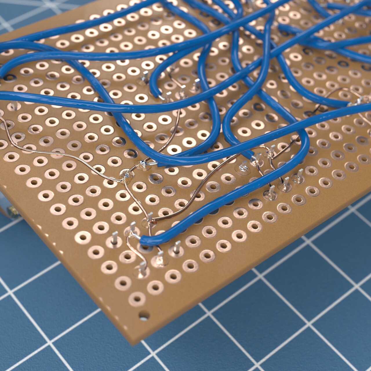
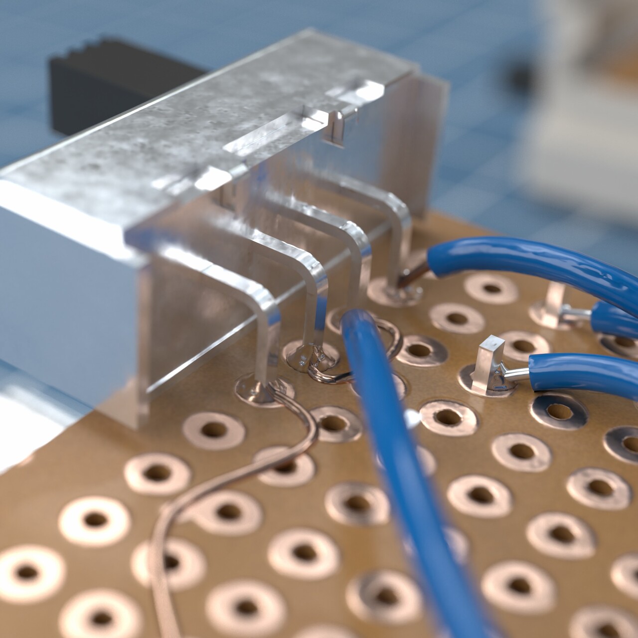
I modeled cables and even I made a one click soldering setup to paint over the board to define solder points of the cables.
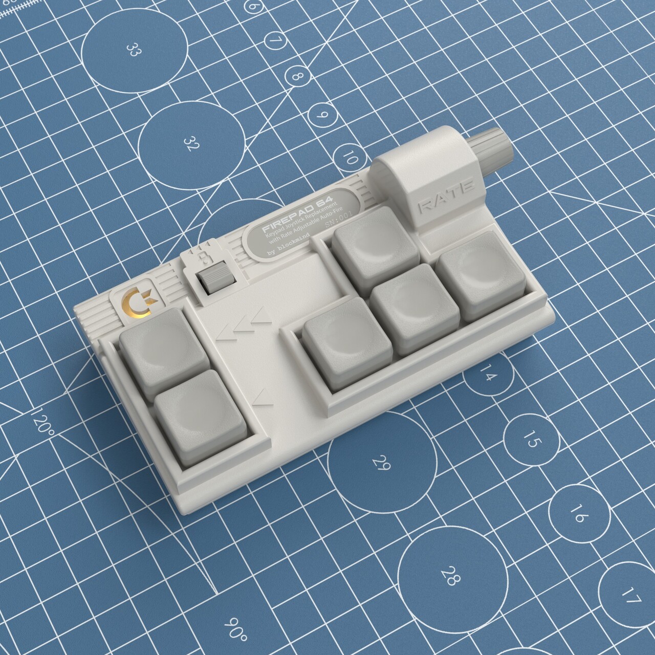
After all texturing this time I rendered detail shots of the artificial one. Which is better on plastics because I materialized it as a plastic injection molding result instead of a homemade 3d print :)
And some comparison with the real product and rendered ones.
Finally I created an animation in marmoset toolbag and applied my Unreal Engine VHS effect to the video get this introduction commercial :)
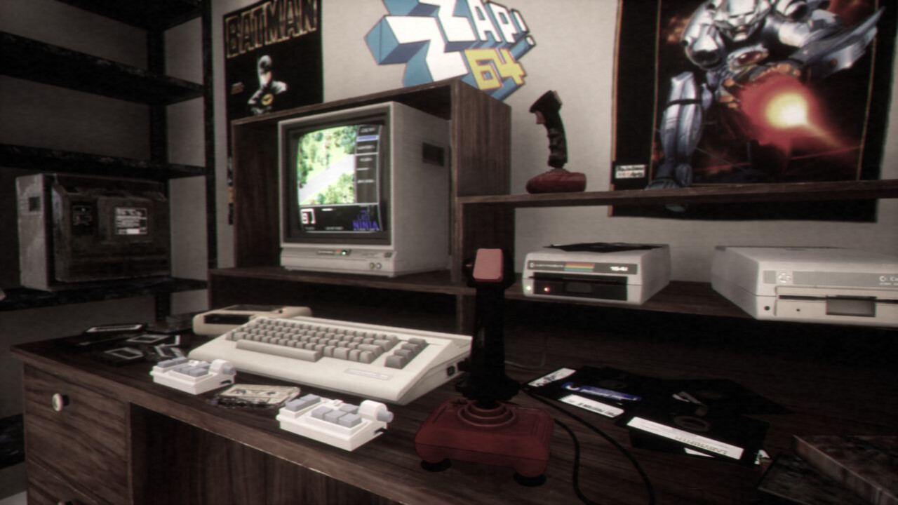
Also I just placed the 3d models to my Unreal Engine retro scene :)
